
A hollow rotary platform is a rotary positioning mechanism with an open center that allows cables, tubing, tooling, or optical paths to pass through the rotation axis. It supports a rotating fixture or workpiece while a motor controls angular movement.
For automation designers, a hollow rotary platform combines useful center access with a supported mounting surface. A suitable hollow rotary platform can simplify fixture integration, organize service routing, and provide repeatable movement between processing positions. Understanding how a hollow rotary platform works helps engineers evaluate its mechanical capacity, motion performance, and compatibility with the complete machine.
A typical geared hollow rotary platform contains an output flange, central bore, support bearing, gear transmission, housing, and motor interface. The flange carries the fixture, while the bearing supports external loads and maintains rotational guidance.
The transmission connects the motor to the rotating output. Depending on the design, a hollow rotary platform may include adjustment features that reduce gear clearance. Sensors, brakes, and encoders may be supplied separately or integrated. A hollow rotary platform is therefore not always a complete driven system: confirm whether the quotation includes only the mechanical unit or also the motor, drive, and controls.
In many geared designs, a motor drives an input gear that transfers motion to a larger gear connected to the output flange. The hollow rotary platform reduces motor speed and increases available output torque within its mechanical limits.
The support bearing guides the flange as the controller commands movement to a target angle. A hollow rotary platform can execute repeated indexing, programmed angular changes, or suitable continuous rotation. However, transmission arrangements differ between products. A hollow rotary platform should not automatically be assumed to use planetary gearing, direct drive, or a particular backlash adjustment mechanism without checking its construction.
For a geared hollow rotary platform, the reduction ratio links motor speed to output speed:
Output speed = motor speed ÷ reduction ratio
For illustration, a 10:1 transmission driven at 1,000 rpm produces a theoretical output speed of 100 rpm. This example does not establish a permissible operating speed for any product.
The approximate output torque of a hollow rotary platform equals motor torque multiplied by ratio and efficiency. Actual capacity remains limited by gear strength, bearings, temperature, and duty cycle. Select a hollow rotary platform using its published operating envelope rather than the ratio alone.
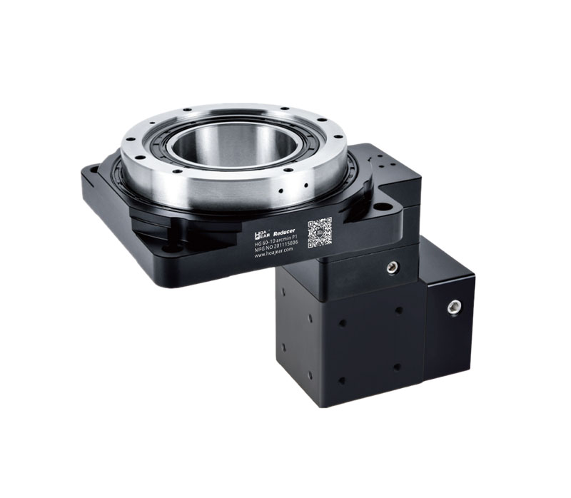
The central opening of a hollow rotary platform provides a route through the rotation axis. This can accommodate pneumatic lines, vacuum tubing, sensor cables, fixed tooling, or a clear optical path, depending on the application.
A hollow rotary platform can reduce congestion around the fixture perimeter, but the opening does not prevent cable twisting by itself. Services connected to rotating components still require controlled movement. For repeated unrestricted rotation, a hollow rotary platform may need an electrical slip ring, fluid rotary union, or another appropriate interface. Bore size must accommodate connectors, bend radius, protective sleeves, and installation access.
The output bearing of a hollow rotary platform must support the fixture and process loads. Some designs use crossed roller bearings, while others use different bearing arrangements. Axial capacity, radial capacity, and permissible overturning moment should be checked separately.
A hollow rotary platform carrying an offset workpiece experiences more than its weight alone. For example, a 100 N force applied 0.15 m from the support produces a 15 Nm moment. Bearing stiffness influences flange deflection under this loading. A hollow rotary platform with sufficient torque may still be unsuitable if its moment capacity or rigidity is inadequate.
Positioning accuracy describes how closely a hollow rotary platform reaches a commanded angle. Repeatability describes how consistently it returns to a position under specified test conditions. These values should not be treated as interchangeable.
Backlash and lost motion affect behavior during direction changes. A hollow rotary platform may have excellent repeatability when approaching from one direction while showing greater error during reversal. Compare measurement direction, load, temperature, and test method. The usable accuracy of a hollow rotary platform also depends on fixture stiffness, mounting quality, motor control, and whether feedback measures the motor or the actual output.
The practical effect of angular error increases with distance from the rotation axis. When evaluating a hollow rotary platform, convert angular specifications into displacement at the actual process radius.
For small angles, tangential displacement approximately equals radius multiplied by angular error in radians. At a radius of 200 mm, one arcminute corresponds to approximately 0.058 mm. This is a geometric example, not a guaranteed machining tolerance. A hollow rotary platform should therefore be assessed at the workpiece location. Choosing a hollow rotary platform using only a small angular number can overlook errors introduced by a large fixture diameter.
A hollow rotary platform may be driven by a servo motor or a compatible stepper motor. Selection depends on speed, acceleration, control requirements, cost, and available torque throughout the operating cycle.
Servo systems use feedback to regulate motion, while open-loop stepper systems can lose position if operating limits are exceeded. Closed-loop stepper configurations provide different capabilities. A hollow rotary platform still requires correct mechanical sizing regardless of motor type. Before specifying a hollow rotary platform, verify flange dimensions, shaft fit, coupling arrangement, motor inertia, drive compatibility, and cable clearance. Motor power alone is insufficient for matching.
Sizing a hollow rotary platform begins with the movement profile. Define the angular travel, acceleration time, maximum speed, deceleration time, dwell, and number of cycles per minute.
Acceleration torque = rotational inertia × angular acceleration
For example, an output inertia of 0.08 kg·m² accelerated at 20 rad/s² requires 1.6 Nm before accounting for friction and process resistance. A hollow rotary platform must also withstand deceleration and reversal loads. Check output torque limits and calculate the corresponding motor demand using ratio, losses, and transmission inertia. A hollow rotary platform selected only for steady running can be undersized during indexing.
Load mass alone cannot determine whether a hollow rotary platform will perform adequately. Rotational inertia depends on how mass is distributed around the axis. Moving components outward can substantially increase the torque needed for the same acceleration.
For a small concentrated mass, inertia is approximately mass multiplied by radius squared. A 1 kg component at 0.2 m contributes approximately 0.04 kg·m². A hollow rotary platform benefits from fixtures that keep unnecessary mass near the center. When choosing a hollow rotary platform, include the mounting plate, clamps, workpieces, tooling, and every rotating accessory in the inertia calculation.
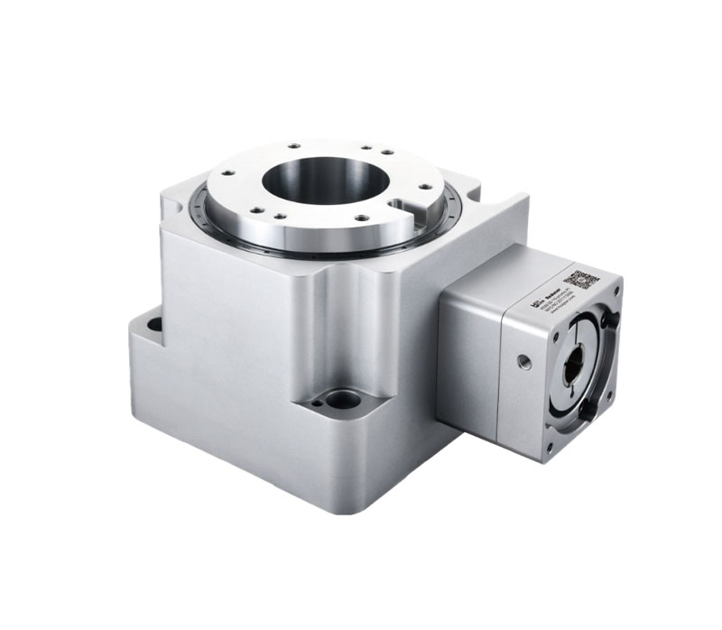
In automated assembly, a hollow rotary platform can orient components for fastening, insertion, dispensing, or inspection. Programmable angles allow the same fixture to present several faces or features to stationary tooling.
Packaging equipment may use a hollow rotary platform to position containers, operate a transfer fixture, or align products between stations. Center access can support vacuum gripping or pneumatic services. However, required throughput depends on more than rotation speed. A hollow rotary platform must complete movement, settle, and hold position while the process finishes. Include loading, unloading, sensor verification, and interlocks when calculating the production cycle.
A hollow rotary platform can rotate a component in front of cameras, gauges, or optical instruments so that several surfaces become accessible. The central opening may also provide space for fixed illumination or an optical path.
For laser marking or related processing, a hollow rotary platform can present successive workpiece faces at controlled angles. Suitability depends on runout, settling, angular accuracy, and synchronization with the process controller. A hollow rotary platform does not automatically provide the accuracy needed for every optical task. Validate the complete fixture and measurement arrangement under representative temperature, loading, and production conditions.
Select a hollow rotary platform by combining torque, inertia, speed, bearing loads, accuracy, bore diameter, and available installation space. Check continuous operation and intermittent indexing separately using the supplier's rating definitions.
Mounting orientation changes the load case. With a vertical rotation axis, workpiece weight mainly creates axial loading; with a horizontal axis, gravity can produce changing drive torque and additional bearing loads. A hollow rotary platform must be rated for its actual orientation. Confirm environmental protection, allowable temperature, lubricant requirements, and access for maintenance before finalizing the hollow rotary platform specification and surrounding machine layout.
Mount a hollow rotary platform on a clean, sufficiently flat, rigid surface. Follow the specified bolt pattern, tightening sequence, and fastener torque. Distorted mounting surfaces can affect bearing behavior and rotational accuracy.
Verify motor alignment and ensure fixture bolts do not interfere with internal parts. Route services through the hollow rotary platform without rubbing, pinching, or excessive bending. Begin commissioning at reduced speed and acceleration, then increase loading progressively. Check direction, travel limits, sensors, vibration, and temperature. A hollow rotary platform should be tested with the actual fixture and workpiece before production acceptance.
The control system determines how a hollow rotary platform references and executes its motion. Depending on the encoder and controller, startup may require homing, reference verification, or recovery of an absolute position.
Motor feedback does not directly measure every source of output error. A hollow rotary platform used for demanding positioning may require output feedback or independent verification. Also distinguish powered holding torque from a mechanical lock or brake. A hollow rotary platform should not be assumed to hold an offset load after power loss. Define the required stopping and holding behavior for the complete machine.
Maintain a hollow rotary platform according to its lubrication, inspection, and service instructions. Check mounting bolts, service routing, seals, noise, temperature trends, and evidence of increased play. Factory lubrication does not imply unlimited service life under every operating condition.
If a hollow rotary platform develops vibration or positioning variation, inspect the fixture, motor coupling, mounting structure, control settings, and load profile before assuming gear damage. Compare symptoms at similar speeds and loads. A hollow rotary platform that becomes progressively hotter or noisier requires investigation, especially after a change in fixture mass, cycle time, or process force.
Before accepting a hollow rotary platform, measure performance with the final fixture, representative workpieces, and normal service routing. Record angular position, settling time, cycle duration, output runout, and housing temperature at defined operating conditions. Repeat the test after thermal stabilization, because a cold demonstration may not represent sustained production. Include movements from both directions and verify the most demanding load position. For a hollow rotary platform used with inspection equipment, compare the complete measurement result against the process tolerance. Retain the data as a maintenance baseline and repeat relevant checks whenever fixtures or operating cycles change.
Some designs can, within specified speed and duty limits. A hollow rotary platform still needs suitable service interfaces if cables or hoses connect to rotating equipment.
No. A hollow rotary platform describes the open-center arrangement; direct drive describes how torque reaches the output. Check the actual transmission design.
Sometimes. A hollow rotary platform offers programmable positioning, but replacement requires checking cycle time, rigidity, torque, dwell requirements, and integration with the machine controls.
Provide the motor details, fixture drawing, load distribution, movement profile, accuracy target, and service routing requirements when requesting a hollow rotary platform. These inputs allow meaningful checks of torque, bearings, control performance, and installation space. A correctly specified hollow rotary platform supports reliable and repeatable positioning while preserving useful access through the rotation axis.
QR Code


This website uses cookies to ensure you get the best experience on our website.


 Español
 Pусский
 Indonesia
 Tiếng Việt


 WhatsApp
 Phone
 E-mail
 Message
Comment
(0)